This is appliable to all fortwo 450s with petrol engines.
The engine uses a separate wiring harness to the rest of the car which links all engine sensors, actuators and the ignition system to the Engine Control Unit (ECU) and the car's main wiring harness. The ECU has two connection sockets: one for the engine wiring harness and a second which connects to the car's main wiring harness.
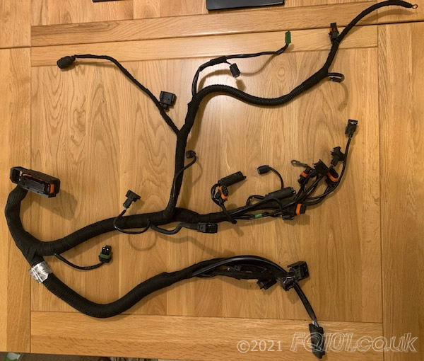
The wiring harness looks as follows. This particular version has been cleaned, repaired where necessary, wrapped in waterproof Tesa Tape and fitted to a 698cc fortwo 450. There are some differences between wiring harnesses, most notably between 599cc and 698cc models but early 599cc models (mk1-3) all had minor differences driven by the need to constantly lower emissions.

With the wiring harness removed, it may not be overly obvious what each connector plug in to. This will hopefullly provide a single source of information you may require when working on the engine harness. With the exception of the lambda sensor circuit on pre-2000 models, all wiring cores are single colour.
The 599cc models all had a separate engine fuse and relay box located beneath the carpet under the left seat. One connector from the engine harness (Connector 'M') plugged into this unit to supply a number of circuits. When this fuse box was removed as part of the intoduction of the SAM unit in 698cc models, an inline connector was provided above the subframe on the left side. This allowed the engine harness to connect directly into the main harness for the car. In both cases, the connector serves the following equipment:
| 599cc fortwos (with electrical centre under left seat): | |||
|---|---|---|---|
| Pin | To | Wire Size | Wire Colour |
| 1 | Ignition Coil Packs | 2.5 (or 3x 1.5) | Green (or 3x White) |
| 2 | Fuel Injectors | 1.5 | Green |
| 3 | Airconditioning compressor | 1.5 | White |
| 4 | - | - | - |
| 5 | Starter motor (start signal) | 2.5 | Blue |
| 6 | Intercooler fan | 1.5 | Yellow |
| 7 | Lambda sensors, cycle valve, vacuum valve | 1.5 | White |
| 698cc fortwos (with connector above subframe): | |||
| Pin | To | Wire Size | Wire Colour |
| 1 | Airconditioning compressor | 1.5 | Blue |
| 2 | Ignition Coil Packs | 1.5 | Red |
| 3 | Fuel Injectors | 1.5 | Green |
| 4 | Starter motor (start signal) | 2.5 | Blue |
| 5 | Intercooler fan | 1.5 | Yellow |
| 6 | Lambda sensors, cycle valve, vacuum valves | 1.5 | White |
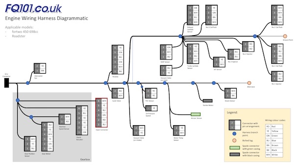
The following image is a diagrammic of the engine wiring harness for a 698cc fortwo (click to enlarge) which shows at which point along the wiring harness various connectors are positioned:
As previously discussed, slight changes have been made to the wiring harness throughout the life of the fortwo 450. However, the ECU has generally remained the same. The following table details the pin arrangement of the engine harness connector.
| ECU Connector Pin | Wire Size | Wire Colour | Function | Destination Connector Pin | Variants |
|---|---|---|---|---|---|
| 1 | 2.5 | Blue | Gear Motor (motor) | 6 | All models |
| 2 | - | - | - | - | All models |
| 3 | 2.5 | Green | Gear Motor (motor) | 1 | All models |
| 4 | 1.5 | Yellow | Clutch Actuator (motor) | 3 | All models |
| 5 | 1.5 | Yellow | Clutch Actuator (motor) | 6 | All models |
| 6 | 0.75 | Yellow | Cylinder No.3 Ignition Coil | 4 | All models |
| 7 | - | - | - | - | All models |
| 8 | 0.5 | Yellow | TDC (Crank Position) Sensor | 2 | All models |
| 9 | 0.5 | Yellow | TDC (Crank Position) Sensor | 1 | All models |
| 10 | 0.5 | Black | Knock Sensor | 1 | All models |
| 11 | 0.5 | Red | Gearbox RPM Sensor | 1 | All models |
| 12 | - | - | - | - | All models |
| 13 | 0.75 | Yellow | Oil pressure switch | - | All models |
| 14 | 0.5 | Yellow | Gear Motor (position sensor) | 3 | All models |
| 15 | 0.5 | Yellow | Gear Motor (position sensor) | 5 | All models |
| 16 | 0.5 | Yellow | Coolant Temperature Sensor | 2 | All models |
| 17 | 0.5 | Yellow | Inlet Air Temperature Sensor | 2 | All models |
| 18 | 0.75 | Yellow | Turbo Lambda Sensor (sensor circuit) | 4 | All models |
| 19 | 0.5 | Yellow | Gear Position Sensor | 2 | All models |
| 20 | 0.75 | Yellow | Throttle (sensor circuit) | 6 | All models |
| 21 | - | - | - | - | All models |
| 22 | - | - | - | - | All models |
| 23 | 0.5 | Yellow | Clutch Actuator (position sensor) | 4 | All models |
| 24 | 0.5 | Yellow | Clutch Actuator (position sensor) | 2 | All models |
| 25 | 0.75 | Green | Cylinder No.3 Ignition Coil | 3 | All models |
| 26 | - | - | - | - | All models |
| 27 | - | - | - | - | All models |
| 28 | - | - | - | - | All models |
| 29 | - | - | - | - | All models |
| 30 | 0.5 | White | Gearbox RPM Sensor | 2 | All models |
| 31 | 0.5 | Black | Gearbox RPM Sensor | Screen | All models |
| 32 | 0.5 | White | Knock Sensor | 2 | All models |
| 33 | 0.5 | Green | Gear Motor (sensor +ve feed) | 2 | All models |
| 34 | 0.5 | Green | Gearbox Temperature Sensor | 1 | Only up to Sept 2000 on 599cc |
| 35 | 0.5 | Green | Gearbox Temperature Sensor | 2 | Only up to Sept 2000 on 599cc |
| 36 | 0.75 | Green | Exhaust Lambda Sensor (sensor circuit) | 4 | From September 2000 on 599cc and 698cc |
| 37 | 0.5 | Green | Throttle (sensor circuit) | 5 | All models |
| 38 | 0.75 | Green | Throttle (sensor circuit) | 3 | All models |
| 39 | 0.5 | Green | MAP Sensor | 3 | All models |
| 40 | - | - | - | - | All models |
| 41 | 0.75 | Green | Lateral accelaration sensor | 2 | 599cc models only |
| 42 | 0.75 | Yellow | Lateral accelaration sensor | 1 | 599cc models only |
| 43 | 0.5 | Green | Clutch Actuator (sensor -ve feed) | 1 | All models |
| 44 | 0.75 | White | Cylinder No.2 Ignition Coil | 3 | All models |
| 45 | 0.75 | White | Cylinder No.2 Ignition Coil | 4 | All models |
| 46 | - | - | - | - | All models |
| 47 | 0.75 | White | Alternator trigger | - | From Sept 2000 on all 599cc and 698cc |
| 48 | 0.5 | White | Vacuum Valve (on intake for cat pre-heater) | 2 | From September 2000 on 599cc and 698cc |
| 49 | - | - | - | - | All models |
| 50 | - | - | - | - | All models |
| 51 | 0.5 | White | Gear Motor (sensor -ve feed) | 4 | All models |
| 52 | 0.5 | White | Coolant Temperature Sensor | 1 | All models |
| 53 | 0.5 | White | Inlet Air Temperature Sensor | 1 | All models |
| 54 | 0.75 | White | Exhaust Lambda Sensor (sensor circuit) | 3 | From September 2000 on 599cc and 698cc |
| 55 | 0.75 | White (Yellow/Brown)* | Turbo Lambda Sensor (sensor circuit) | 3 | All models |
| 56 | 0.75 | White | Throttle (sensor cicuit) | 2 | All models |
| 57 | 0.5 | White | MAP Sensor | 2 | All models |
| 58 | - | - | - | - | All models |
| 59 | - | - | - | - | All models |
| 60 | 0.5 | White | Gear Position Sensor | 3 | All models |
| 61 | - | - | - | - | All models |
| 62 | - | - | - | - | All models |
| 63 | 0.75 | Blue | Cylinder No.1 Ignition Coil | 4 | All models |
| 64 | 0.75 | Blue | Cylinder No.1 Ignition Coil | 3 | All models |
| 65 | 0.5 | Blue | Vacuum Valve (on inlet for cat-preheater air pump) | 2 | Only on 698cc models |
| 66 | 0.75 | Blue | Exhaust Lambda Sensor (heater circuit) | 2 | From September 2000 on 599cc and 698cc |
| 67 | 0.75 | Blue (Brown/Pink)* | Turbo Lambda Sensor (heater circuit) | 2 | All models |
| 68 | 0.75 | Blue | Cycle Valve | 2 | All models |
| 69 | - | - | - | - | All models |
| 70 | 0.75 | Blue | Fuel Injector No.3 | 2 | All models |
| 71 | 0.75 | Red (Blue)* | Fuel Injector No.2 | 2 | All models |
| 72 | 0.75 | Blue | Fuel Injector No.1 | 2 | All models |
| 73 | 0.75 | Blue | Throttle (actuator motor) | 4 | All models |
| 74 | 0.75 | Blue | Throttle (actuator motor) | 1 | All models |
| 75 | 0.5 | Blue | Clutch Actuator (sensor +ve feed) | 5 | All models |
| 76 | 0.5 | Blue | MAP Sensor | 1 | All models |
| 77 | - | - | - | - | All models |
| 78 | - | - | - | - | All models |
| 79 | 0.5 | Blue | Gear Position Sensor | 1 | All models |
| 80 | 0.75 | Blue | Lateral Accelaration Sensor | 3 | 599cc models only |
* up to September 2000


