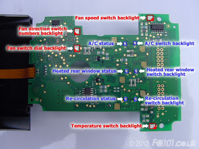
LEDs needed for graphic backlights: 3x PLCC-2 SMDs
LEDs needed for button backlights (including status indicators): 6x 0805 SMDs.
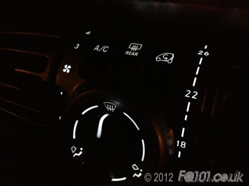
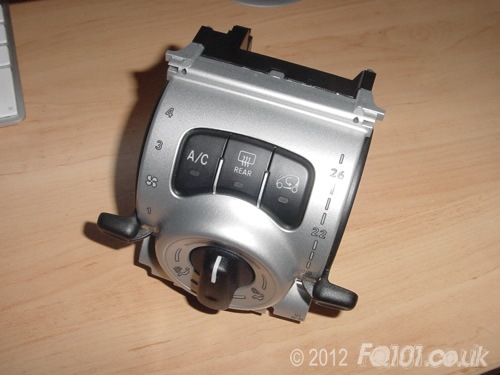
The environmental control unit is the module that sits in between the two central air vents. This module contains all the functions for adjusting the interior air conditioning (cooling, air distribution, fan speed, temperature etc.). It is a programmable unit, like the SAM, ECU, etc. so take care when working on it.
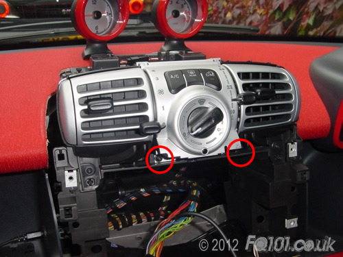
To remove the module, you will need to first remove the radio.
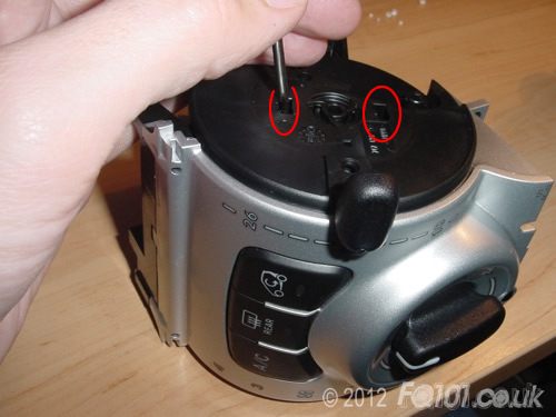
The selector module is secured by 2x TX10 screws shown below.
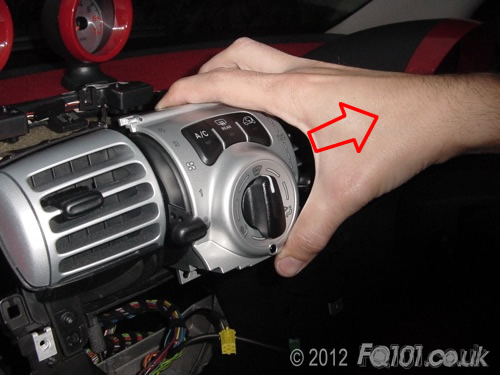
Pull the module from the bottom and it will unclip from the top. Don't pull it too hard at this stage.
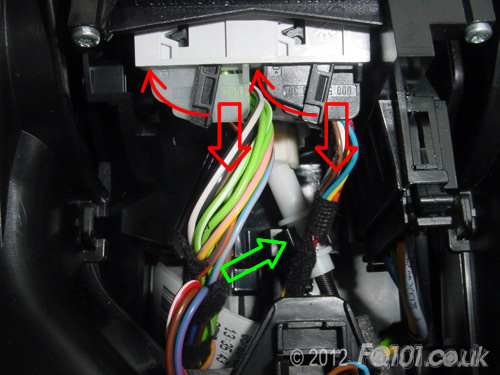
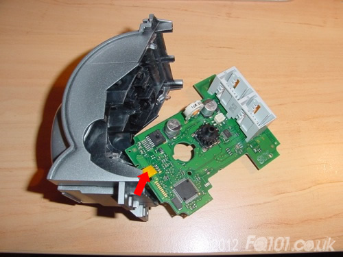
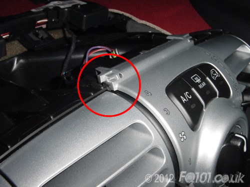
Remove the large connector from the left hand side as shown below. This is the connector for the fan speed switch.
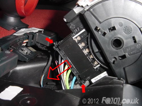
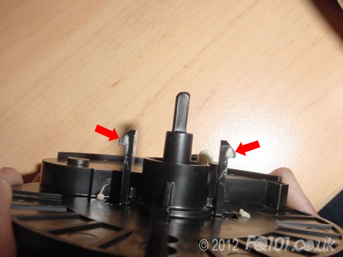
At the back of the module, there are two latching connectors which need to be removed. Swing down the lever (thin red arrow) and the connector will pull free (large red arrow).
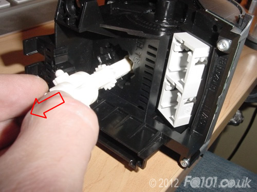
You also need to remove the direction adjuster arm from the back of the module. If you pulled the module too hard you might find that this has disconnected from the other end. If it has, don't worry, it's just quite tricky to refit!
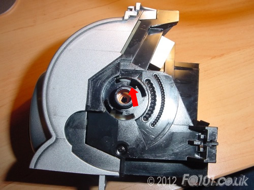
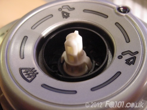
To remove the adjuster arm from the module, unclip the white arm from the black clip (green arrow). Pull the ball joint out of the back of the module.
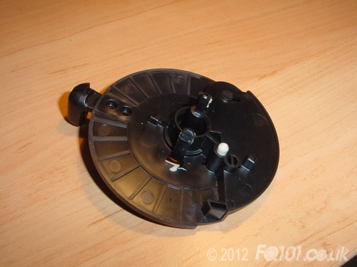
The module will now be free.
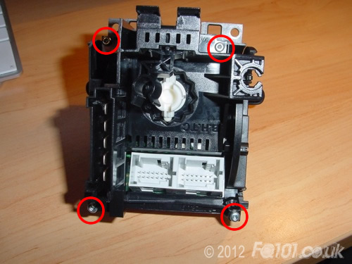
Turn the module over and you will see 4 TX8 screws in the following locations. Undo these.
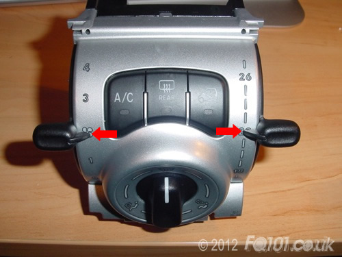
On the front of the module, slide both selector swithes so that they at their half way point (fan speed 2 and temperator 22 degrees).
For each switch, push a small screwdriver in the slots as shown. You are trying to clip the switch from the body of the module. It might be worth scrolling down and looking at the next 3 pictures to see what you are trying to do.
These are the clips that you are trying to overcome.
There are two recesses in the arced groove as shown below. This is why you need to position the sliders at their half way points before you try and remove them.
When you remove the switch, be careful not to lose the white bullet spring that enables the switch to click when you move it.
Pull off the direction switch. This is quite hard and you need to be quite forceful! you may find gripping the switch at the top and bottom in order to get more grip (i.e. at 90 degrees to the picture below).
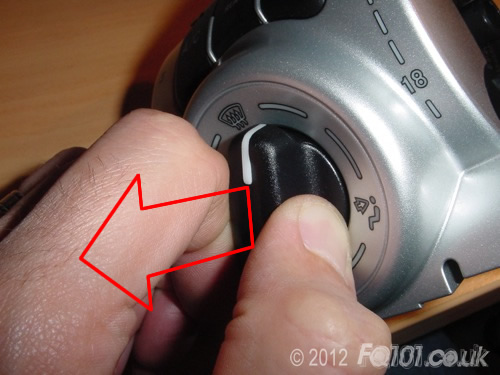
The white selector arm will be free to slide out from the back of the module.
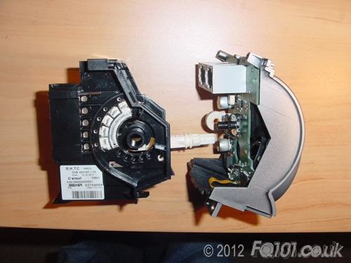
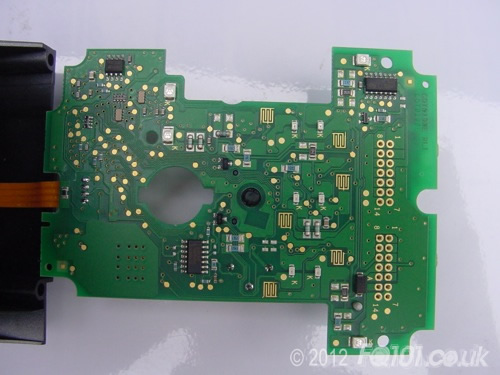
The module will now separate revealing the PCB.
The PCB will come away freely but be careful as the sensor attached to the ribbon track (arrowed) will not.
Take your PCB and begin your LED changes.
Click the following picture to make larger. Red LED symbols are PLCC-2 LEDs, blue symboles are 0805 LEDs.
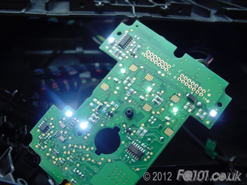
Test the LEDs before you reassemble. Attach the two latching connectors and turn on the lights to bring on the backlights.
Reassemble the module and refit. Remember to clip in the top section correctly.
A vastly improved look.