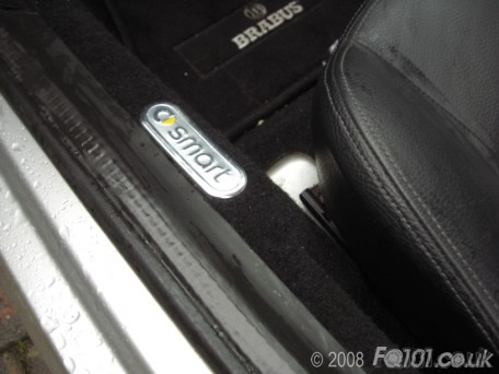
This small piece of trim pictured here is available from smart under the following part number: 0012921V002.
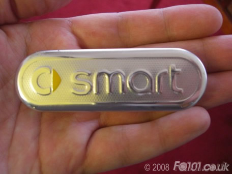
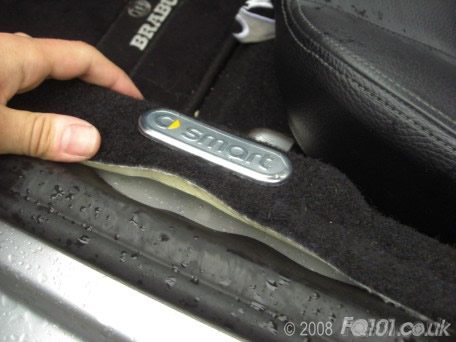
These badges are both exactly the same and sit on the edge of the carpet, meaning this is one of the very first things you see when the cars door is opened.
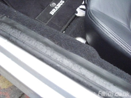
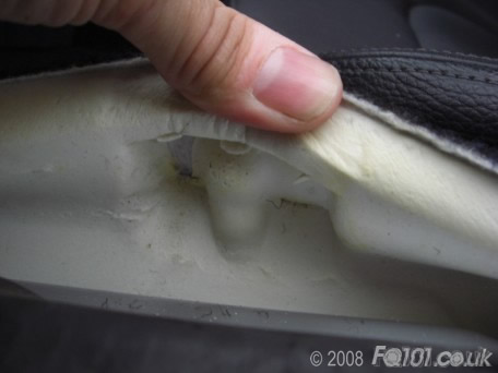
Lift the rubber door seal enough to un-tuck the carpet, giving you access to the underside.
When you lift the carpet it will become apparent where the badge locates exactly.
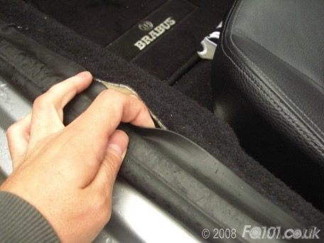
The carpet is perforated allowing the badge to be quite simply pushed all the way through.
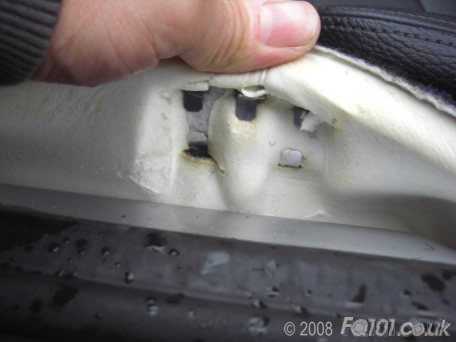
Now the badge is where its meant to be, fold the tabs under tight to secure it in place.
Tuck the carpet back into place and straighten the door seal so it sits flush.