


This guide focuses on cars which do not have the base wiring already installed. If you do have the wiring then the task is much more straightforward and will be covered in a later guide.
Introduction:
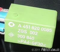
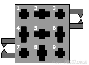
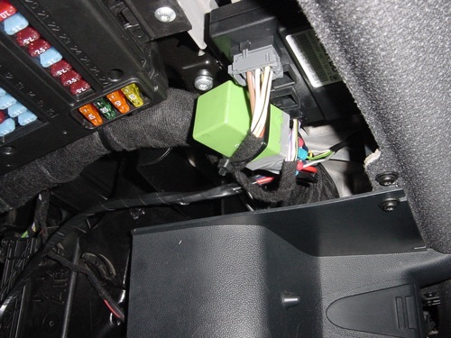
The core element to the heated seat control system, is the relay module. The fortwo 450 and Roadster heated seats have similar shaped modules but require one module per seat. The fortwo 451 only requires one module for both seats and therefore operates differently to the other cars. Therefore, if you are sourcing components, you can only use the bright green fortwo 451 module which looks as follows:
On cars which have heated seats already installed at the factory, the relay module plugs into a connector that is hidden behind the dash. If you can obtain this connector, great. If not, don't worry - you just have to wire it up slightly differently. More on that later!
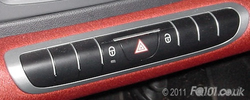
If you haven't got heated seats, your switch strip will look as follows:
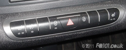
You'll need one with the heated switch buttons at either end, shown as follows:
And fundamentally, you will need the heated seats themselves!
2. Theory and circuitry
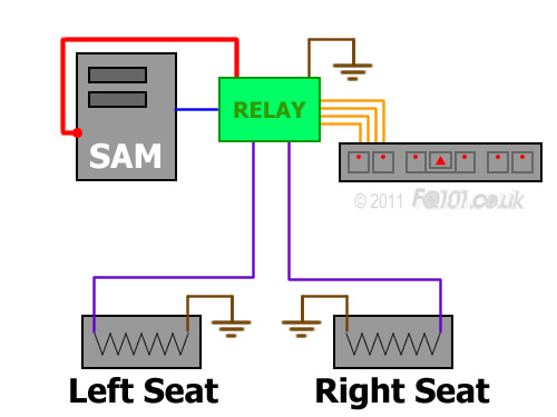
The following simplistic diagram shows how you need to connect everything to create a stock looking installation.
Depending on whether or not you have just the relay module or the additional connector as well, you will notice that each terminal is numbered. The connector numbering is looking from the top down whereas the green relay module's ordering is taken from looking at the pins (bottom up).

With two different numbering systems, there are two different circuit diagrams that are applicable. Wiring thicknesses are indicated by the coloured letters next to the wires and are as follows:
| Code | Wire CSA (sqmm) |
|---|---|
| A | 2.5 |
| B | 1.0 |
| C | 0.5 |
If you have just the relay module:

If you have the relay module and base connector:
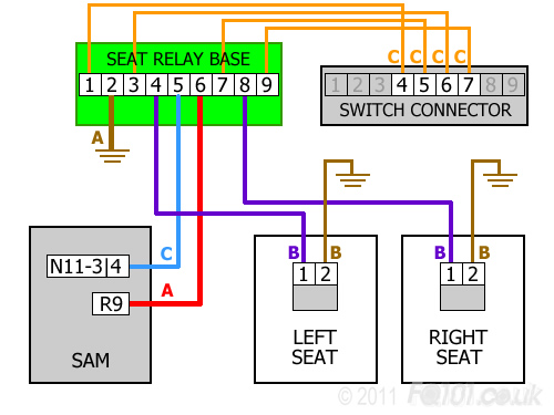
- The relay module requires a constant live. This is taken from expansion slot R9 on the front of the SAM. This allows the heated seat buttons to be pressed when the key is at position '1' and stops the relay voltage from floating when the engine is off.
- A switched live signal feed is taken from connector N11-3 pin 4 on the back of the SAM. This ensures the relay module doesn't actually heat the seats until the engine is running.
- 4 links are required between the switch connector and the relay module. Two wires are for each seat button: full power and half power. The switch strip gets it's power from elsewhere.
- Each seat has a single power feed. The sensation of full power and half power is achieved by varying the amount of time the heater is on.
3. Installation
We are going to start with the switch strip. Remove your old one by pulling it out of the dash. The positions of where the heated switches need to be are circled.

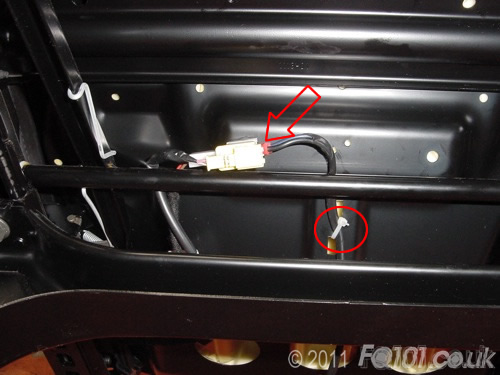
Remove the connector on the back by pushing the white clip as shown by the solid arrow. You will then be able to swing down the grey latch and the connector will pop out of the switch panel.
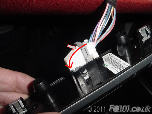
To remove the connector from the casing, use your thumbnail to pull back the white tab (arrowed below). At the same time, there is a hole on the other side of the case which you can use to push the connector out (it will slide out towards you in the following image):

With the connector removed, turn it so that you can see the numbers '1' and '9'. Their locations are indicated approximately by the white numbers below. The controls for heated seats need to be wired into positions 4, 5, 6 and 7, shown in red. These connectors are Tyco AMP and you can buy the inserts from many electronics distributor (Maplin's for example). Alternatively, you can harvest them off an old wiring loom with a sufficient length of wire attached.

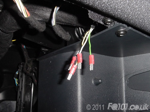
With your new wires connected, poke the wiring through the dash and bring it out near to the SAM. We wrapped the wires together with PVC tape to make a rudimentary loom.
One the end of each wire, crimp a miniature female spade connector. Note which wire corresponds to which pin position on the switch strip connector.
This completes the switch wiring. You can now connect your new heated seats switch strip and fit it back into the dash.
Now let's concentrate on the seat wiring.
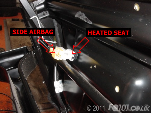
Take you new heated seats and look underneath. You will see a yellow connector for the side airbags and a white connector for heated seats.
For both seats, we found that a miniature female spade connector fitted the seat connector perfectly. For both seats, crimp both spade connectors to wires and run these back to the SAM. For completeness, we wrapped both wires together in PVC tape. At the seat position we cable tied the new loom to the seat base to prevent the connectors from being strained.
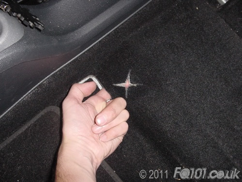
Under each seat position, there is a perforation in the carpet through which the wiring should run.
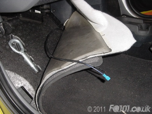
Run the wiring along the edge of the foot well as and tie it to other wire looms where you can. Be careful not to prevent removal of the polystyrene box in the passenger footwell. Keep the wiring close to the centre console.
We brought both live connections from both seat positions and taped these together with the wires that link to the SAM. On each one we crimped standard sized female spade connectors. This end will connect to the relay module:
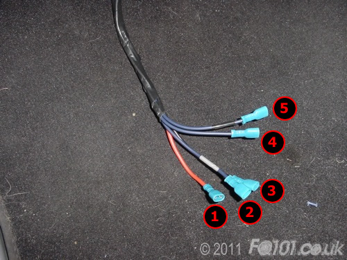
1. = Constant live from R9 on the SAM
2. = Switched live signal from SAM
3. = Relay module ground connection
4. = Passenger heated seat
5. = Driver heated seat
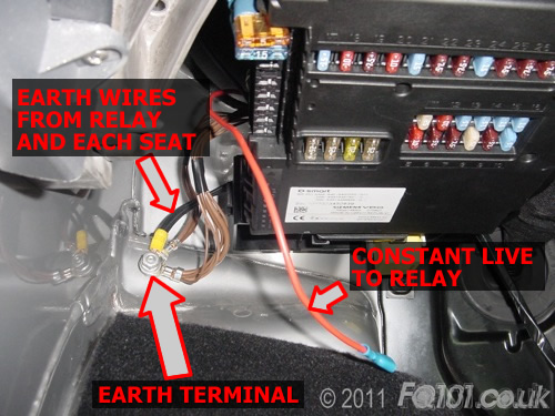
We used the ground point next to the SAM to ground both seats and the relay module itself. It was easier to do this than try to get access to the ones in the footwells. The constant live was brought out to the expansion slots on the left of the SAM and fitted with a standard sized female spade connector.
To connect the switched live wire, we lowered the SAM by unclipping it from the bottom and pushing it up at the top. This unclips it from the top hinge allowing clear access to the wiring on the back.
Fortunately connector N11-3 is the nearest and is characterised with a brown base. Identify the fourth wire along from the left. It should be coloured black/grey.
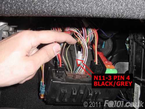
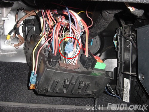
Splice or scotch clip the wire from the relay module into this wire (as circled). Providing the key is out of the ignition, there is no harm doing this with the battery connected.
At the relay module position, connect up the wiring. If you have just the relay module on its own, use the top circuit diagram above. If you have the relay module base as well, following the second circuit diagram. In this case, we plugged all the spade connectors directly into the back to the relay module.

Cable tie the module to the main wiring loom so that it is secure.
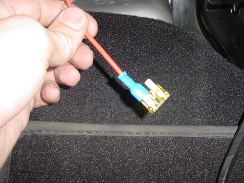
Now that everything is wired up, time to connect the main power. Use a 20A fuse as shown. Plug the other side of the fuse into R9 on the SAM unit. You can use the approved smart fuse carriers if you wish.
Switch on the ignition and test! Pressing the button once brings on full power. Pressing it a second time switches it to half power. Pressing it a third time switches the seat off.


