

Parts Required:
- Replacement 599cc turbo
- 2x exhaust studs
- 2x exhaust collar nuts
- 7x M6 manifold studs
- 7x M6 manifold collar nuts
- 6x water pipe transfer washers
- 2x oil pipe transfer washers (depends)
- 599cc turbo heatshield
Tools Required:
- 3/8" socket set with a extension bar
- E8 socket for above
- E10 socket for above
- 10mm hex socket for above
- 13mm hex socket for above
- 17mm hex socket for above
- Flat blade screwdriver
- Crosshead (Philips) screwdriver
It is not uncommon to have to replace the fortwo turbo assembly, especially for a 599cc fortwo. The main issue concerns the integrity of the manifold which is prone to cracking under the cyclic heat stress that it is subject to. This may cause the car to surge under acceleration. Pictures of cracked turbos can be found here.
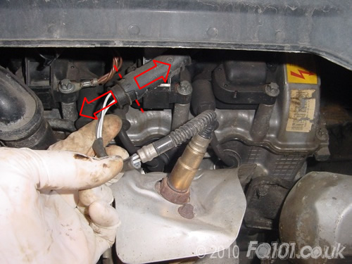
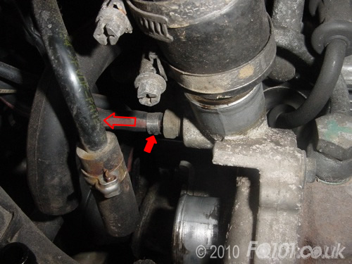
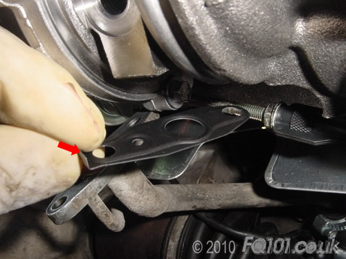
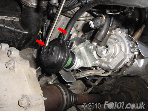
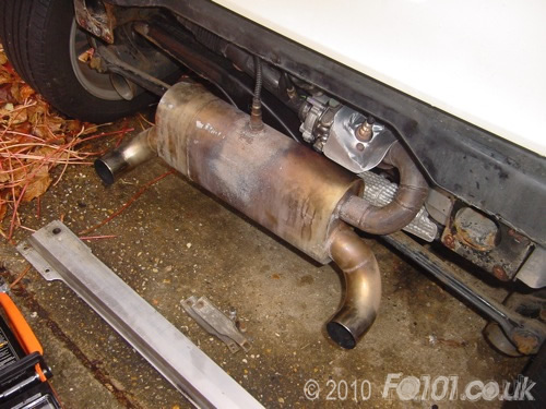
To replace the turbo, start by removing the rear panel, crash bar and exhaust. Then disconnect the turbo lambda sensor as shown. You may need to unclip this from the wiring loom that is located above.
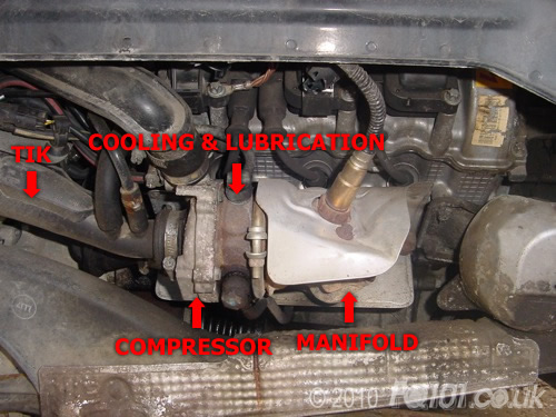
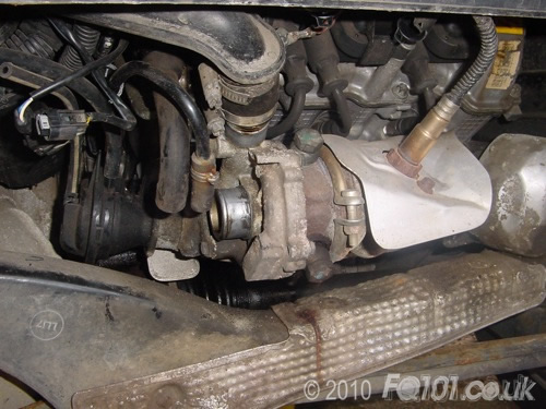
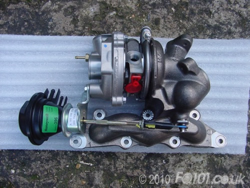
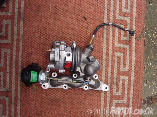
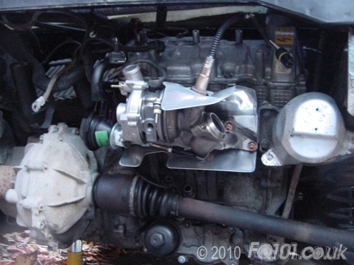
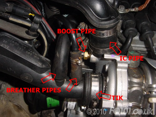
The turbo assembly comprises three sections as shown below. The whole assembly attaches to the cylinder head by the manifold. Carefully look at the manifold and you might see where the exhaust air has been blowing through any cracks.
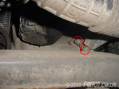
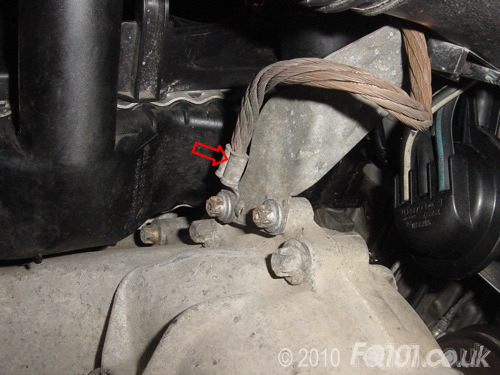
Start by disconnecting the air lines at the compressor end. To gain some play in the TIK pipe, unbolt the two E10 bolts that attach the TIK bracket to the gearbox. One of these bolts also secures the engine earth wire.
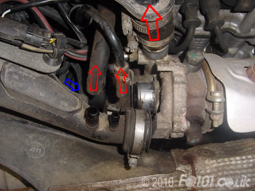
With a bit of play in the TIK, you can now disconnect it from the compressor end of the turbo. To do this, pull off the two breather pipes from the base of the TIK. Then undo the jubilee clip from the where it connects to the turbo. As you pull the TIK away, keep an eye out for the vacuum pipe that connects to the back - shown by the blue arrow. Carefully pull this free from the wastegate actuator (no need to remove it from the TIK).
Finally, loosen the lower jubilee clip from the intercooler pipe and pull it free from the top of the turbo.
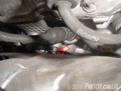
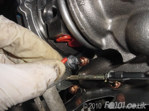
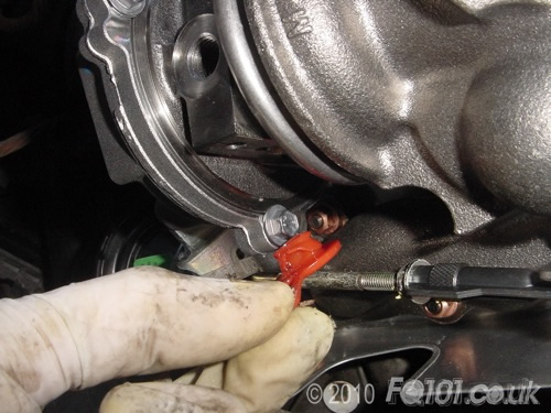
Next to where the intercooler pipe was connected, there is a high pressure boost line which needs to be disconnected. This is held in place with a metal clip (solid red arrow) which can be gently prised off with a flat blade screwdriver.
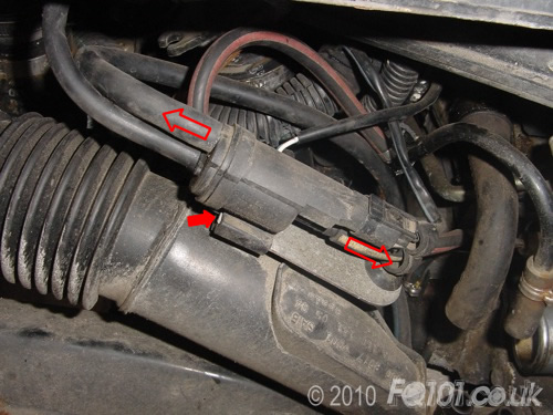
Attached to the TIK is an air line switching valve which has air lines connected to the turbo. Disconnect the ones as shown below. If it makes it easier to work, remove the valve by pressing the clip (shown in solid red) and sliding it off the bracket. You may chose to remove the TIK as well as this does provide a bit more space.
This completes disconnection of the air side of the turbo.
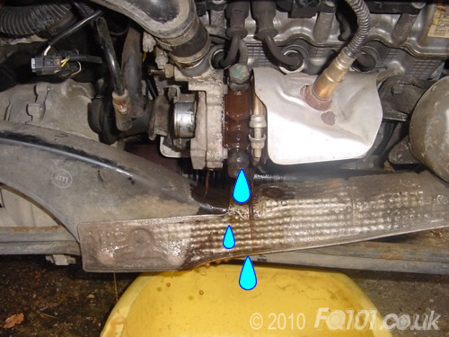
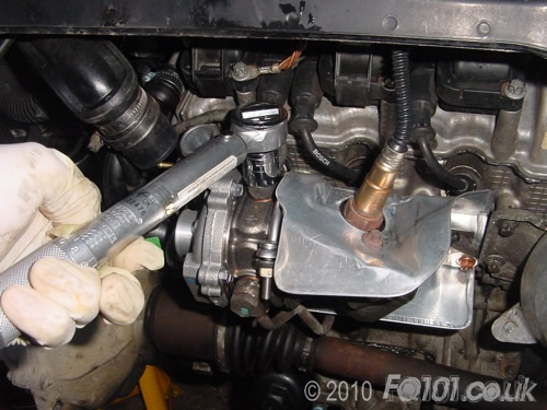
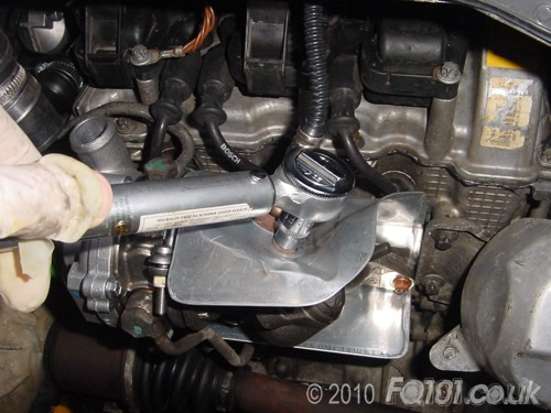
Now disconnect the cooling system from the turbo body. Start with the top banjo bolt indicated as follows. Use a 17mm hex socket for this. Ensure that you place a bowl under the turbo to catch the coolant.
Note: Ensure that animals are not exposed to coolant as the embedded antifreeze is highly poisonous.
Allow the coolant to drain. Remove the banjo bolt and the copper washers.
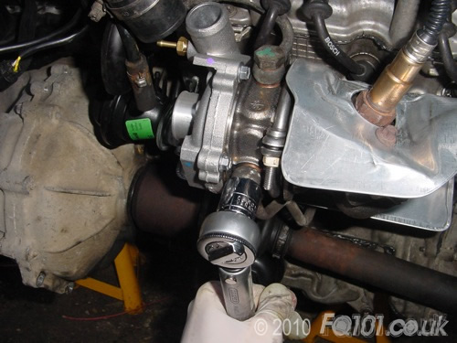
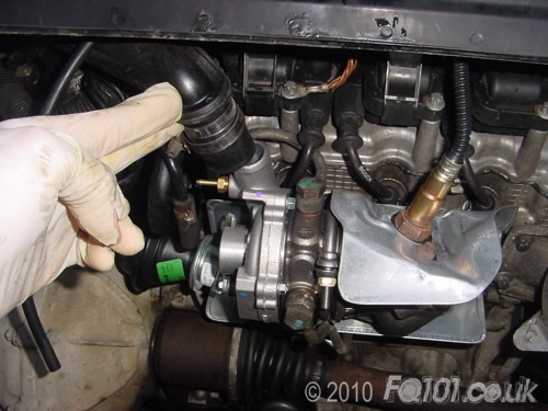
Now repeat with the lower pipe.
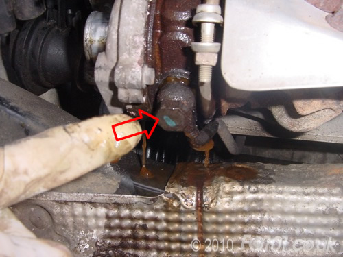
The lower pipe connects to the front face of the engine block beneath the turbo. Undo this bolt as before.
Now remove the water pipe.
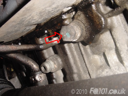
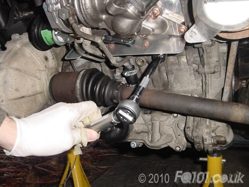
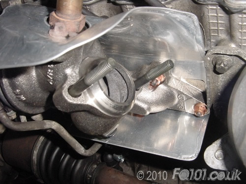
Beneath the turbo is the oil line which is secured with two E8 bolts shown as follows. These are awkward to get to, so you will either need a small ratchet or lower the rear K-bar in order to gain enough access.

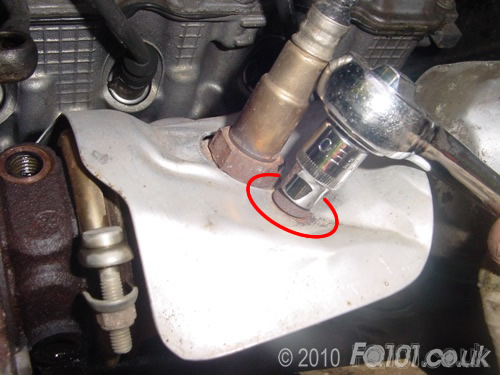
With an E10 socket, undo the bolt that secured the heatshield to the turbo manifold.
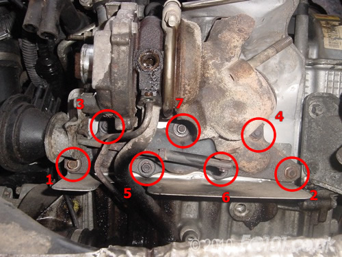
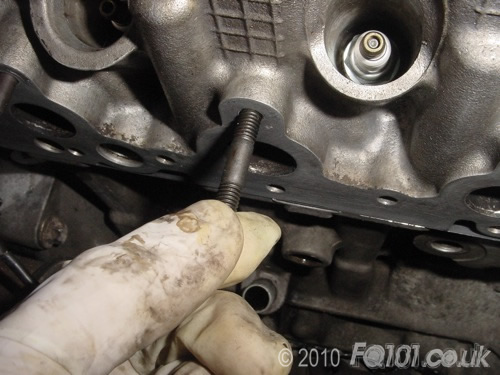
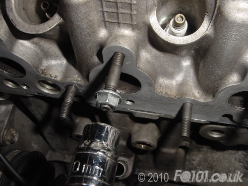
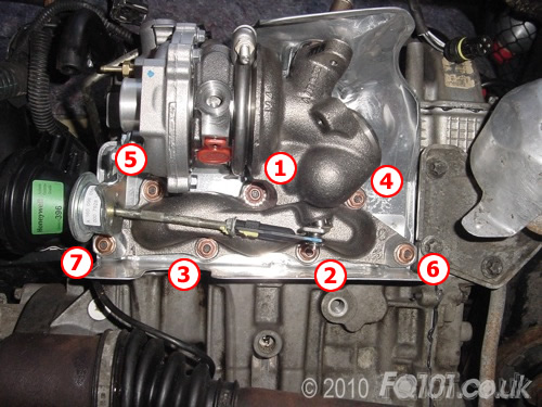
Now, with all lines disconnected, you can begin to unbolt the turbo manifold from engine block. It is not essential, but it is good practice to undo the nuts in the order shown below. Be careful when you do this as the turbo studs will have become brittle and are prone to snapping. Apply a steady force and they should come free. If they snap, you will be able to remove them from the cylinder head with a pair of mole grips or stud extractor.
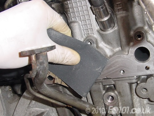
As the turbo and heatshield come away from the engine, keep an eye out for the metal plate on the back of the heatshield as this has a tendancy to snag on the studs:
The turbo will now be free to remove.
If there are any studs left in the head, try to remove these before fitting the new turbo. By leaving the old ones in place, you risk snapping them when you fit the new nuts. It is easier to remove a snapped stud while there is space rather then when the turbo is half fitted!
Clean up the mounting face of the turbo with some fine grade wet and dry.
New turbo assemblies come complete with a wastegate actuator so uyou don't need to transfer this over from the old turbo. In this guide we are fitting a the later design 599cc turbo which has a reinforced manifold. You can see this reinforcement in the casting under the wastegate actuator arm.
Before fitting the turbo to the car, we recommend fitting the lambda sensor first. In this way, you will avoid placing stress on the turbo mounting studs. Use a 22mm ring spanner to remove it from the old turbo and fit on your new one. Depending on the age of the sensor, you may chose to replace it.
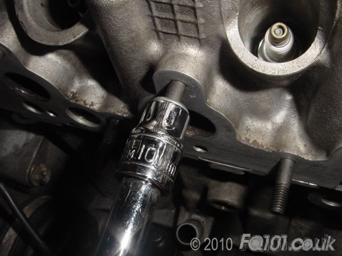
Fit the new M6 turbo studs into the cylinder head as follows:
To wind them fully home, use a spare M6 nut (not one of the new copper ones!) and wind this on to the other end as follows:
Now tighten the nut until it stops. It will then wind the stud fully into the head.
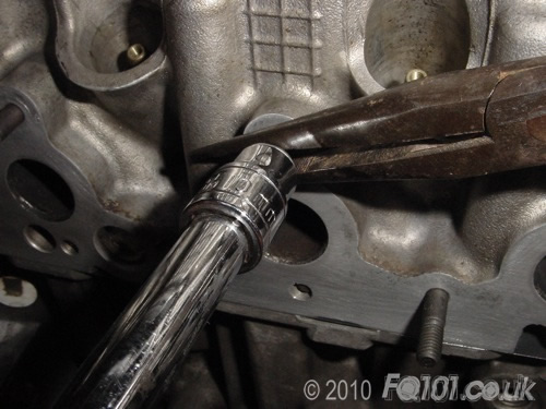
Use a pair of long nosed pliers and while gripping the stud, undo the nut.
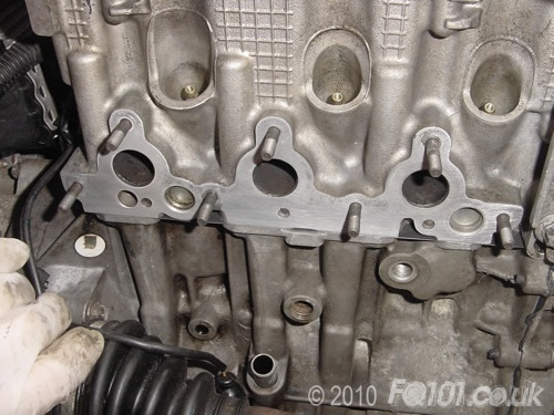
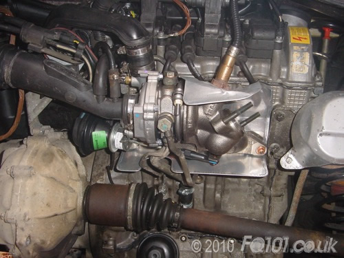
Repeat for all studs so that all 7 are fitted. In the following picture, the sparkplug leads and the oil feed pipe to the turbo have been removed for other reasons outside of this guide. For turbo fitting, you don't have to do this. However, should you remove the oil feed line, you will need to fit two new oil transfer washers.
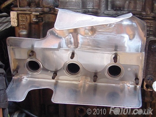
Slide the heatshield in place and allow it to rest on the studs.
Now offer up the turbo. Remember to feed the lambda sensor lead through the hole first. Fit the new copper washers by hand so that they prevent the turbo from falling.
Tighten the nuts with a 10mm hex socket so that they are almost secure. Then tighten each nut to 16Nm in the order shown. It is important to follow this order so that the heatshield is compressed evenly and makes a good seal.
Pull out the plastic peg that is fitted to the oil feed point.
Now pull out the rest of the oil plug and wipe away the storage oil that will come out.
If you have removed the oil feed pipe, fit this first. The banjo bolt that secures to the engine block must be tightened to 10Nm so that it seals with the new oil transfer washers.
Fit the new oil seal as shown in the following picture. The bent end must point upwards as indicated by the arrow. Refit the two E8 bolts and tighten to 7.6Nm.
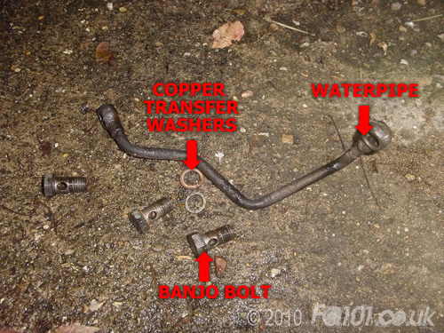
Fit the upper water pipe and ensure that you put a new copper water transfer seal either side of the pipe before refitting the banjo bolt. Tighten the bolt to 19Nm using a 17mm socket.
Refit the lower water pipe and fit the copper seals as before. Tighten again to 19Nm. In the following picture you can see the new copper seals either side of the water pipes.
Finally, repeat for the other end of the water pipe.
Tighten the heatshield bolt to 8Nm.
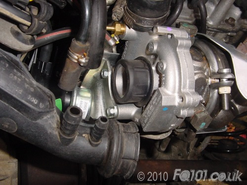
Refit the intercooler pipe and ensure both jubilee clips are tight.
Fit the large black vacuum pipe and the small black/white pipe as shown. For clear details on how to reconnect the vacuum system pipes, refer to this guide.
If you have removed the TIK, fit this back to the airbox and reconnect the pipes to the cycle valve and air line switching valve. This gets fiddly so be patient! Ensure that you fit the metal clips to the ends of the black/red boost pipes as follows:

Remove the rubber seal from the end of the TIK and fit it on to the end of the turbo compressor. Apply some water to the rubber as this will make the TIK easier to fit over the seal.
Push the TIK back on to the turbo and ensure that the rubber seal doesn't get snagged as this can potentially cause damage when the engine is running. Remember to connect the blue/black vacuum pipe
Fit the boost pipe onto the top of the compressor and ensure it is fitted with a metal clip. Push the lower breather pipes onto the base of the TIK. Finally, check that all jubilee clips are nice and tight.
Fit the short threaded end of the exhaust studs into the turbo manifold and refit the exhaust.
Fit the TIK backet back to the gearbox ensuring that the engine earth strap is securely in place.
Plug the lambda sensor back into the wiring and double check the following:
- Turbo nuts are torqued correctly
- Oil feed pipe is secured to the engine and torqued correctly to the turbo
- All three water pipe banjo bolts are torqued correctly
- Intercooler pipe is secured to the top of the turbo compressor
- TIK is secured to the inlet of the turbo
- Breather pipes are connected to the TIK
- Long Red/Black boost pipe is connected to the compressor
- Short Red/Black boost pipe is connected to the wastegate actuator
- Thick black vacuum pipe is connected between the wastegate actuator and the switching valve
- Black/White vacuum pipe is connected between the wastegate actuator and the switching valve
- Black vacuum pipe is connected between the cycle valve and the wastegate actuator
- Blue/Black vacuum pipe is connected between the back of the TIK and the wastegate actuator
- Both the cycle valve and switching valve are plugged in to the wiring loom
- Exhaust studs are fitted
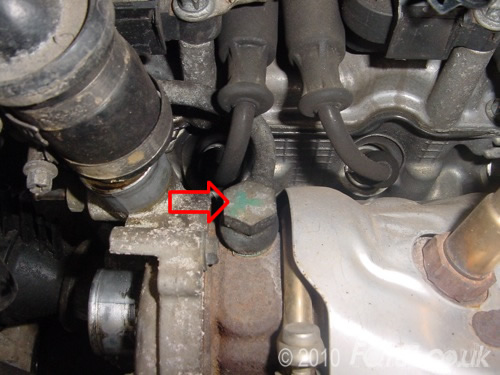
- Heatshield bolt has been fitted next to the lambda sensor
Now refit the exhaust and bleed the cooling system using the methodology towards the end of this guide. Once you are happy, start the engine and perform a test drive.
To maximise the life of the turbo, always allow the engine to run for about a minute after stopping the car. This will allow the manifold to cool progressively and limit thermal stresses.


